The Teardown
Diagnotics and Remediation.
From Dan's Digital Archaeology
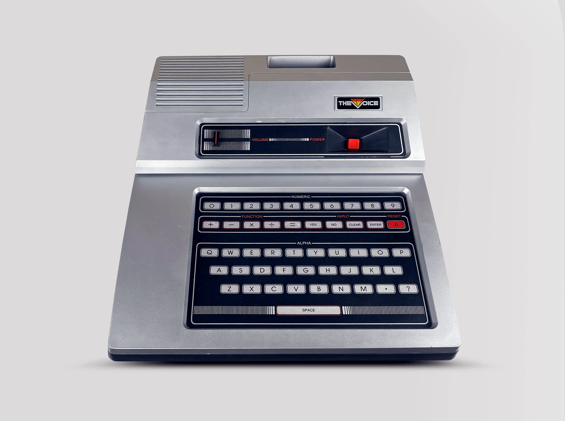
A couple months ago I ran across a post on the AtariAge forums by Dale Crum about an unusual Odyssey2 that he found. The system looked like a stock O2 with the Voice module screwed to it. Inside the base unit was a extra circuit board that connected to the Voice with a ribbon cable. After studying the pictures of the unit we came to the conclusion that this was a system used to develop sound samples for the O2 Voice games.

The Odyssey2 Voice uses an General Instruments SP0256 Voice Processor chip. Normally this chip uses specially manufactured serial ROMs for the voice data. These chips were very efficient for the production units but they would have made it hard to develop the sound samples. General Instruments provided a solution to this in the form of the Speech Field Development Board. This board contained a special chip that allowed the SP0256 to use standard EPROMs instead of serial ROMs which provided an easy way to develop new voice samples.
The system basically worked ok, but there was no sound from the Voice module when playing voice enabled games. Dale decided to send the system to me so I could try to repair it and also dump the EPROMs from the development board in case they had samples on them that had never been released.
The first step was to dump the EPROMs, since they were standard 2732 EPROMs this was a simple task. We were also fortunate that the EPROMs had their checksums values written on the labels so I could quickly confirm that the data on the chips was valid. We were hoping to find something interesting on them but in the end we found that the data on the chips was an exact match for what is in the production version of the Voice module.
With the EPROMs dumped I turned my attention to getting the voice module to work. The system had a second AC adapter that was being used to power the development board. I quickly realized that this adapter was dead, I got no voltage out of it. This was stock O2 adapter and since they are sealed I decided not to try to open it to see what went wrong. I went through my stock pile of AC adapters and found another one with the same specs.
With the new AC adapter hooked up I tried KC’s Crazy Chase again to test the voice. A few of the voice samples played but others were missing and in some cases the wrong sample played. Before I could start troubleshooting this problem I lost all the sounds from the Voice again. Checking the replacement AC adapter I found it had also died. Since this one was mine I decided to cut it open and see what went wrong. These are AC-to-AC adapters so there is not much to them, and I found that a thermal fuse in the transformer had blown.
I dug up another transformer, in this case a standard NES supply which provides the same voltage but had a little higher current rating. I did some careful testing to see if the development board was drawing to much current, but eventually determined that current draw was fine. I decided to resume troubleshooting and did not encounter any more power supply problem. The first replacement AC adapter I used was old so I can only assume that it was not in good condition and the board just put a little to much load on it.
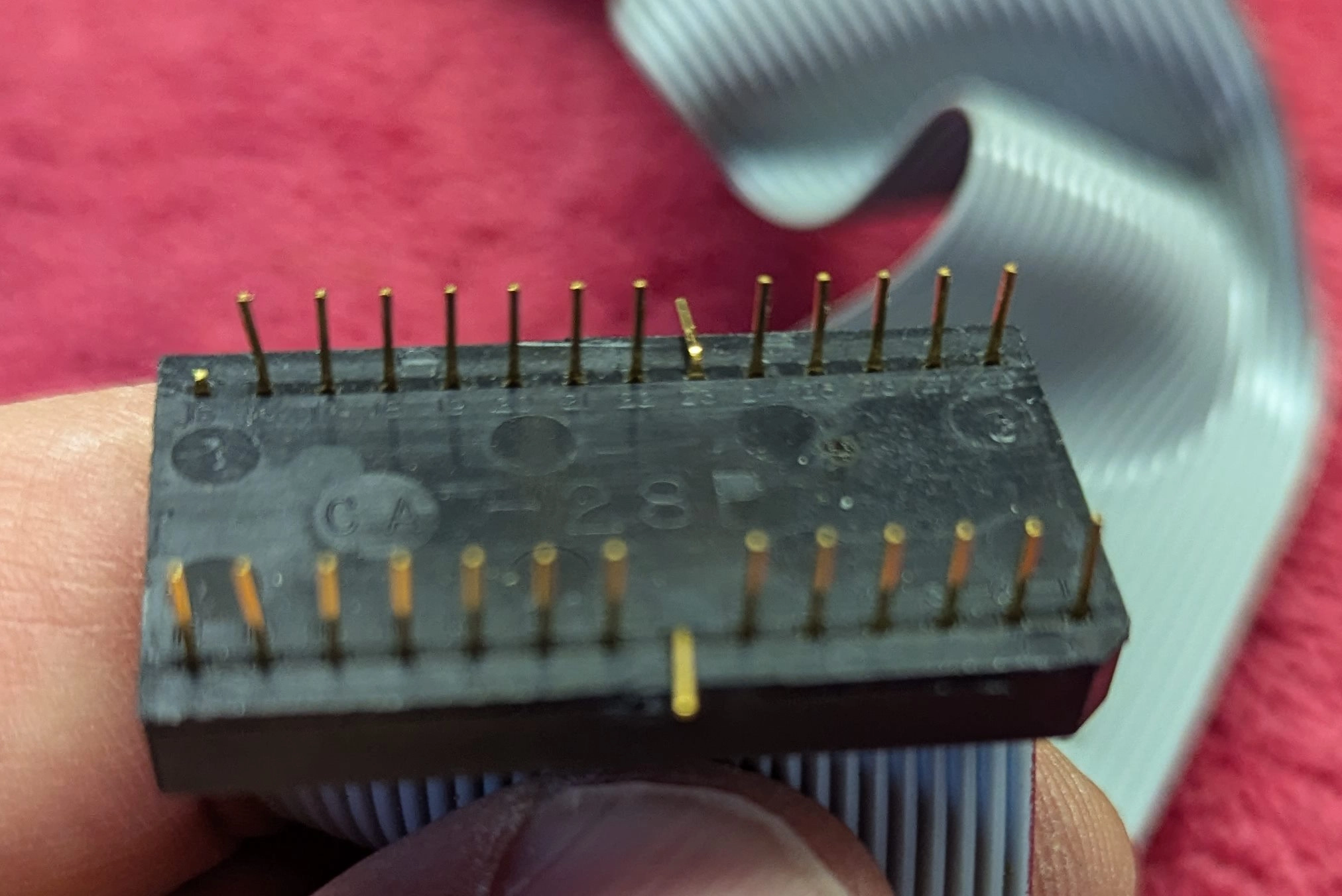
With the power supply issue resolved I went back to troubleshooting the Voice problem. I started to probe the signals that are used to address the SP0256 and found one line that didn’t look right. I inspected the ribbon cable that runs from the development board to the Voice module. Here is a picture of the connector that plugs into the socket where the SP0256 normally is on the Voice.

I was initially concerned about the two bent over pins, but this turns out to be normal. These are the pins for power and ground, and since the development board has it’s own power supply there we bend over to isolate the two power supplies. The real problem was the broken pin the the upper left. This was one of the addressing pins which explains why the incorrect samples were played at certain times. The is a pretty unique cable so replacing it would not have been easy so I needed to try to repair it. I gouged out a little of the plastic at the based of the pin and then soldered on a pin I took from a spare connector. It wasn’t a great repair but this connector won’t often be disconnected so it should work. With that pin repaired everything worked perfectly.
Additional Details
The only Schematics you’re looking for.
Dan Boris has kindly provided the following schematics.